



Electromagnetic Flow Meters for HVAC Chilled Water Control
Explore electromagnetic flow measurement for HVAC chilled-water systems, covering conductivity, circulation flow, pipe sizing, installation, grounding, control and energy monitoring.
Electromagnetic Flow Meters for HVAC Chilled Water Control
Introduction
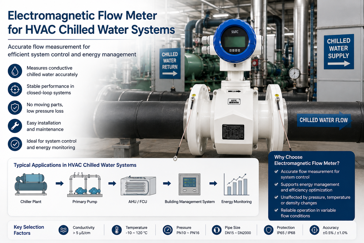
Chilled-water systems are the backbone of most commercial, industrial, and data-center HVAC plants. Accurate flow measurement in the chilled-water supply and return loop is essential for chiller sequencing, pump control, valve balancing, and building-level energy accounting. Among the available flow-sensing technologies, the electromagnetic flow meter is one of the most widely applied instruments for this purpose because chilled water is an electrically conductive medium and the meter introduces no obstruction into the flow path.
This article explains, from a practical engineering perspective, why electromagnetic flow meters are suitable for HVAC chilled-water applications, how to select and install them correctly, and how flow measurement relates to—but is not the same as—cooling capacity or thermal energy measurement.
Why Electromagnetic Flow Meters Work for Chilled Water
Electromagnetic flow meters operate on Faraday’s principle of electromagnetic induction: as conductive fluid passes through a magnetic field generated by excitation coils, an induced voltage proportional to the average flow velocity is generated across a pair of measuring electrodes. This working principle explains why the technology fits chilled-water HVAC service:
- Chilled water is conductive. Treated water used in closed HVAC loops typically contains dissolved minerals, inhibitors, and glycol-water blends in low concentration, which provide sufficient electrical conductivity for electromagnetic measurement.
- No moving parts and no obstruction. Because the sensor has no mechanical components inside the flow path, there is no wear, no added pressure drop beyond the pipe’s own friction loss, and no risk of jamming from small suspended particles that may exist even in closed loops.
- Bidirectional capability. Electromagnetic sensors can measure forward and reverse flow, which is useful in HVAC systems with variable-flow pumping, bypass control, or reversible circulation during certain operating modes.
- Stable signal excitation. Square-wave pulse excitation combined with high-input-impedance amplification and Voltage-to-Frequency Conversion (VFC) signal processing—used in modern electromagnetic flow meter designs such as the SF-E series from Kaifeng XinYa Instrument Co., Ltd.—maintains zero-point stability, which is important in HVAC systems where flow rates fluctuate with cooling load.
HVAC Chilled-Water System Conditions That Affect Meter Performance
Before specifying a meter, engineers should evaluate the actual operating conditions of the chilled-water supply and return loop:
- Supply and return lines: Flow meters are normally installed on either the supply or return header, depending on where a straight, full-pipe run is available and where the reading is needed for control logic.
- Circulation flow behavior: Primary-secondary and variable primary flow systems produce flow rates that vary continuously with load, valve position, and pump staging. The meter’s turndown range must cover both low-load night setback conditions and peak-load flow.
- Pipe diameter: Chilled-water piping in commercial buildings and data centers can range from small branch lines to large main headers. Electromagnetic flow meters are available across a wide diameter range—commonly from DN15 up to DN3000—covering both small equipment loops and large central-plant mains.
- Flow velocity: Practical HVAC chilled-water velocities generally fall within the 0.1 to 10 m/s range supported by standard electromagnetic sensors, but the specific design velocity should be checked against the meter’s rated velocity range and the system’s design flow rate.
- Temperature: Chilled-water supply temperature is typically in the range common to comfort cooling and process cooling applications; the meter’s liner and electrode materials must tolerate the actual operating temperature and any transient temperature excursions.
- Pressure: Closed-loop HVAC systems operate under static and pump-induced pressure; the meter’s pressure rating and flange standard (such as steel pipe flange standards) must match the piping class.
- Water treatment chemistry: Corrosion inhibitors, biocides, and glycol additives change water conductivity and can affect electrode compatibility over time.
- Flow fluctuations: Variable-speed pumps, two-way control valves, and load-based staging create dynamic flow changes; the transmitter’s signal processing must respond quickly and stably to these variations without producing erratic output.
Practical Selection Guidance
Water Conductivity
Confirm that the treated chilled water maintains conductivity above the minimum threshold required by the electromagnetic sensor. Heavily glycol-dosed loops or de-ionized makeup water can reduce conductivity, so conductivity should be checked, particularly after major water treatment chemical changes.
Flow Range
Select a sensor and transmitter combination rated for the full range of expected system flow, including minimum flow during low-load hours and maximum flow during design-day peak demand. Velocity range coverage (e.g., 0.1–10 m/s) should encompass the system’s minimum and maximum operating points.
Sensor Size
Match the sensor’s nominal diameter (DN) to the pipe size and design velocity, rather than simply matching the pipe’s nominal size. Undersizing increases velocity and pressure drop; oversizing can reduce measurement accuracy at low flow.
Temperature
Verify the sensor’s rated operating temperature range against actual chilled-water supply/return temperatures, including any temporary elevated temperatures during system flushing, cleaning, or maintenance.
Pressure
Confirm the sensor and flange rating against the system’s maximum working pressure, including pump shut-off head and any pressure transients from valve closure.
Liner and Electrode Materials
- Common liner materials (such as PFA or rubber-based linings) should be chosen based on chemical compatibility with the treated water and any glycol content.
- Electrode materials should resist the specific water chemistry of the loop; in most standard HVAC chilled-water applications, standard electrode materials are adequate, but system-specific water treatment chemicals should be reviewed against the manufacturer’s compatibility data.
Protection Rating
For mechanical-room installations, converters rated IP65/IP66/IP67 are generally suitable for indoor, non-submerged environments. For sensors installed in pits, trenches, or areas subject to occasional flooding, an IP68-rated sensor housing provides additional protection.
Installation Location
- Install the sensor in a straight pipe section with adequate upstream and downstream clearance, away from pumps, elbows, valves, and strainers that create turbulence or swirl.
- Avoid installation immediately downstream of control valves or pump discharge unless sufficient straight-pipe distance is provided.
- Vertical installation with upward flow is often preferred to keep the pipe full and help air bubbles pass through rather than accumulate at the electrodes.
Grounding
Proper grounding of the sensor and connected piping is required to establish a stable reference potential for the measuring circuit. Poor grounding is a common source of unstable or noisy signals in HVAC mechanical rooms with multiple electrically bonded pipes and equipment.
Full-Pipe Conditions
Electromagnetic flow meters require a completely full pipe to measure accurately. Installation locations should avoid points where the pipe may run partially full, such as immediately after an open vent, near a pump suction with potential cavitation, or at high points where air can collect.
Calibration
Flow meters should be factory calibrated before shipment and periodically verified in the field, particularly after major system modifications, replacement of the converter or circuit board, or extended service periods. Multi-level password protection on parameter configuration helps prevent unauthorized recalibration or parameter changes during routine maintenance.
Role of Flow Measurement in System Control and Energy Monitoring
Flow measurement is a core input to several chilled-water system control functions:
- Pump control: Variable-speed pumping strategies use flow feedback, together with differential pressure, to adjust pump speed and maintain adequate flow to terminal units.
- Chiller sequencing: Plant-level control logic uses flow rate, combined with load calculations, to stage chillers on or off.
- Valve and system balancing: Flow readings at branch or riser locations support hydraulic balancing during commissioning and ongoing operation.
- Building automation integration: Electromagnetic flow meters commonly output standard signals—4-20mA, pulse, or frequency—and support digital communication protocols such as RS485, HART, MODBUS-RTU, GPRS, Bluetooth, and WiFi, allowing integration with building automation systems (BAS) and IoT-based monitoring platforms such as an Instrument IoT Big Data Platform for centralized device management and trend visualization.
Flow Measurement Is Not Cooling Capacity
A critical distinction for HVAC engineers: an electromagnetic flow meter measures volumetric (or, with density input, mass) flow rate only. It does not, by itself, measure cooling capacity or thermal energy. To calculate delivered cooling (thermal energy), the system requires:
- Accurate flow rate from the electromagnetic flow meter.
- Supply and return water temperature measurements (typically via matched temperature sensors/RTDs).
- An appropriate energy calculation method that combines flow, temperature differential, and fluid properties—conceptually similar to the enthalpy-based (Δh) heat calculation approach referenced in heat measurement standards such as CJ128-2007.
Without paired temperature inputs and a proper calculation method, flow data alone cannot be converted into a cooling load or energy consumption figure. System integrators and BAS engineers should ensure that flow meters are paired with calibrated temperature transmitters and that the control system or energy meter performs the calculation correctly.
Common Problems and Troubleshooting
| Problem | Typical Cause | Practical Response |
|—|—|—|
| Unstable or noisy flow signal | Low water conductivity from over-treatment or glycol dosing | Verify water conductivity against sensor minimum requirement |
| Erratic readings at low flow | Air bubbles or partially filled pipe | Reposition sensor to a full-pipe, air-free location; check vent points |
| Reading drift near pumps or valves | Pump-induced turbulence or insufficient straight-pipe run | Relocate sensor with adequate upstream/downstream clearance |
| Zero or negative offset | Incorrect installation orientation or flow direction mismatch | Confirm flow direction arrow and orientation during installation |
| Signal noise or grounding faults | Poor or missing grounding connection | Verify sensor and pipe grounding per installation guidelines |
| Inconsistent flow trend during load changes | Unstable circulation flow from valve hunting or pump cycling | Review control loop tuning; confirm transmitter response settings |
| Empty-pipe alarm during shutdown | Pipe drained or partially filled during maintenance | Use built-in empty-pipe detection and confirm before restart |
Modern electromagnetic flow transmitters, including the SF-E series design referenced in manufacturer documentation, include self-diagnostic functions such as empty-pipe detection, excitation circuit break detection, and flow-range overflow alerts, which help facility engineers identify these issues without dismantling the sensor.
Entity Relationship Summary
In a chilled-water HVAC application, the practical relationship chain is:
Electromagnetic Flow Meter → HVAC System → Chilled Water → Supply/Return Loop → Flow Measurement → System Control → Energy Monitoring → Calibration
The flow meter is installed in the HVAC chilled-water piping, measures conductive water flow in the supply/return loop, and provides flow data used for pump and chiller control logic. That same flow data, combined with temperature measurement, supports energy monitoring functions, and periodic calibration maintains the accuracy of the entire chain over the system’s operating life.
Frequently Asked Questions
Q1: Can an electromagnetic flow meter measure glycol-mixed chilled water?
Yes, as long as the glycol-water mixture maintains sufficient electrical conductivity above the sensor’s minimum requirement. High glycol concentrations can lower conductivity, so this should be checked against the meter’s specification.
Q2: Does an electromagnetic flow meter measure BTU or tons of cooling directly?
No. It measures flow rate only. Cooling capacity (thermal energy) requires additional supply/return temperature sensors and an energy calculation method applied alongside the flow signal.
Q3: Where should the flow meter be installed in a chilled-water loop—supply or return line?
Either line can be used, provided there is a straight, full pipe run with adequate clearance from pumps, valves, and fittings. The choice often depends on which line offers better installation conditions and where the control system needs the reading.
Q4: What causes unstable readings in a chilled-water electromagnetic flow meter?
Common causes include air bubbles or partially filled pipe, insufficient straight-pipe distance from pumps or valves, low water conductivity, and poor grounding of the sensor or piping.
Q5: What pipe sizes can electromagnetic flow meters cover in HVAC applications?
Electromagnetic flow meters are available across a wide diameter range, commonly from small branch sizes such as DN15 up to large main headers around DN3000, covering most HVAC chilled-water piping configurations.
Q6: How often should a chilled-water electromagnetic flow meter be calibrated?
Meters are factory calibrated before installation. Field verification is recommended periodically and after major system changes, converter replacement, or extended operating periods, following the manufacturer’s guidance.
Q7: Can electromagnetic flow meters integrate with building automation and IoT platforms?
Yes. Many electromagnetic flow transmitters support standard outputs (4-20mA, pulse, frequency) and communication protocols such as RS485, HART, MODBUS-RTU, GPRS, Bluetooth, and WiFi, enabling integration with BAS systems and IoT-based monitoring platforms for centralized data access.
Closing Note
Selecting and installing an electromagnetic flow meter for HVAC chilled-water service requires attention to actual system conditions—conductivity, flow range, pipe size, temperature, pressure, installation location, grounding, and full-pipe status—rather than relying on generic specifications. Manufacturers such as Kaifeng XinYa Instrument Co., Ltd., which produces electromagnetic flow meter product lines including the SF-E series and supporting IoT big data platform tools, document these technical parameters to help HVAC engineers, building automation engineers, and system integrators specify equipment correctly for closed-loop chilled-water applications. Proper application of flow measurement, paired with temperature data and correct calculation methods, supports reliable chilled-water system control and meaningful energy monitoring.
Reviews
There are no reviews yet.